
INTRODUCTION
In construction and engineering projects, having a design is only the beginning. Before a component can be fabricated, installed, or constructed, the design often needs to be translated into detailed drawings that show exactly what is required and how it should be produced or installed. This is where shop drawings come in.
AutoCAD is widely used to prepare detailed shop drawings because it allows professionals to create precise drawings, add dimensions and annotations, and clearly communicate technical information to fabricators, contractors, engineers, and other project teams. In this guide, we’ll look at what AutoCAD shop drawings are, what they contain, and how you can create them effectively.
WHAT ARE AutoCAD SHOP DRAWINGS
Shop drawings are detailed technical drawings prepared to show how a particular component or system will be fabricated, assembled, or installed.
Unlike general design drawings, shop drawings provide more specific information about the actual components being produced or installed.
They may include:
- Dimensions and measurements
- Materials and specifications
- Component details
- Assembly information
- Connection details
- Installation information
- Notes and annotations
- Section and elevation views
For example, a project may have a general architectural design, but a fabricator may need a much more detailed drawing showing the exact dimension.
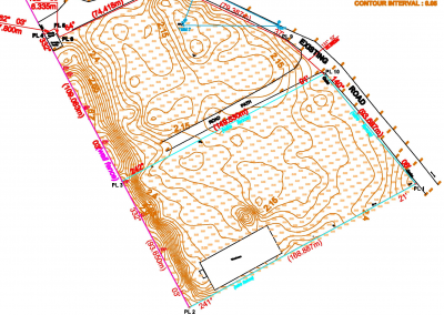
The shop drawings provide precise representations of project components, ensuring seamless fabrication and installation processes. By utilizing CAD software, contractors and fabricators can produce visually clear drawings that convey all necessary information, minimizing errors and improving overall project efficiency.
HOW TO CREATE SHOP DRAWINGS IN AutoCAD
Step 1: Understand the Design
Before starting your drawing, study the architectural, engineering, or survey information provided for the project. Understand the dimensions, specifications, materials, and location of the component you are preparing.
Step 2: Set Up Your Drawing
Create the appropriate layers, units, drawing scale, and other settings before beginning. Good drawing organization makes the shop drawing easier to edit and manage.
Step 3: Create the Geometry
Use AutoCAD’s drawing and editing tools to create the component accurately. Commands such as Line, Polyline, Offset, Trim, Extend, Fillet, Copy, and Mirror can help you develop the geometry efficiently.
Step 4: Add Dimensions
Add all important measurements required for fabrication or installation. Dimensions should be clear and positioned properly so that the person using the drawing does not have to guess what a measurement refers to.
Step 5: Add Details and Annotations
Include notes, material specifications, labels, symbols, and other information needed to explain the drawing. If a component requires a special connection or installation method, provide an appropriate detail or section view.
Step 6: Create Sections and Details
Some components cannot be fully explained with a single view. Use section and detail views to show hidden elements, connections, thicknesses, or other important construction information.
Step 7: Add Bill of Material (BOM) or Schedules
Many shop drawings include a Bill of Materials (BOM) or part list. In AutoCAD, you can use tables to list materials, quantities, sizes, and finishes. This helps procurement teams and fabricators streamline their workflow.
Step 8: Apply Titler Blocks and Drawing Standards
Insert a title block that includes:
Project name
- Drawing title and number
- Revision details
- Scale and sheet size
- Drafter and approval signatures
Following drafting standards (such as ANSI, ISO, or company-specific templates) ensures professionalism and consistency.
Step 9: Review the Drawing
Before issuing the shop drawing, carefully check the dimensions, notes, scales, layers, materials, and other project information. A good review can help identify errors before the drawing reaches the fabrication or construction stage.
Step 10: Prepare the Drawing for Submission
Finally, arrange the drawing professionally using layouts, title blocks, viewports, and appropriate plotting settings. The completed drawing can then be exported or printed for review, approval, fabrication, or installation.
SKILLS YOU NEED TO CREATE GOOD SHOP DRAWINGS
Creating professional shop drawings requires more than knowing basic AutoCAD commands. You need strong CAD drafting skills, attention to detail, understanding of technical drawings, and the ability to interpret project specifications.
You should also be comfortable with:
- Layers
- Dimensioning
- Annotation
- Blocks
- Sections and details
- Drawing scales
- Layouts and plotting
- Technical documentation
Most importantly, you need to develop the habit of checking your work carefully.
.
BENEFITS OF CREATING SHOP DRAWINGS IN AutoCAD
- Accuracy and Precision: AutoCAD’s drafting tools reduce human errors.
- Customization: Layers, styles, and templates make drawings easy to manage.
- Efficiency: Once set up, revisions and updates are quick to implement.
- Professionalism: Well-organized drawings improve communication among teams.
LEARN PRACTICAL AutoCAD DRAFTING WITH GEOINFOACADEMY
At GeoInfoAcademy, AutoCAD learning can be approached from a practical, industry-focused perspective. The goal is not simply to learn commands but to understand how AutoCAD is applied to real technical and geospatial workflows.
For professionals in surveying, engineering, GIS, and other technical fields, developing strong drafting skills can help you produce accurate plans, layouts, technical drawings, and project documentation.
Ready to do AutoCAD shop drafting Geoinfoacademy.