Togo Digital Terrain Model Project
Learn MoreINTRODUCTION
This report discusses in full all image processing and image analysis methodologies, as well as the results obtained at the end of the project. The Geoinfotech Resources Limited GIS team was charged with generating a 3D Surface Model from the given source information.
A BRIEF DESCRIPTION OF THE PROJECT
We intend to produce a 3D Surface Map to assist in the analysis of the region’s overall elevation trend and to describe the slope of the study area.

WHAT IS A 3D SURFACE MAP?
Surface maps are three-dimensional representations of a grid file. Surface maps are also referred to as “rendered surfaces.” 3D surface maps, as opposed to 3D wireframes, employ solid color fill, feature concealed line removal, and can have images layered on them.
To better understand what a 3D Surface Map is, we can visualize a 3D surface map as a representation of a physical area or terrain that has been scaled down (reduced in size).
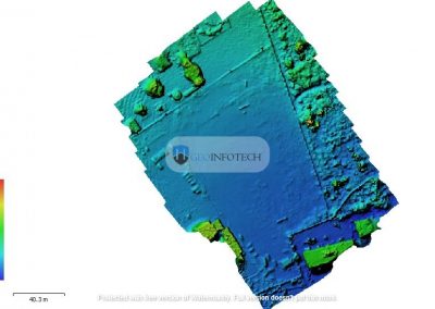
In this project, the chosen map view is a perspective view of the 3D Surface Model. The 3D Surface Model was created using a DTM source material. The primary material color style utilized for both the map and the color scale is the terrain.
METHODOLOGY
The 3D Surface Model was created using Golden Software Surfer and a DTM data source material. To obtain a 3D Surface Map, the user needs to have a basic understanding of the software; thus, a number of procedures were followed.
HOW TO CREATE A 3D SURFACE MAP
PROCEDURE
- The user must launch Surfer and create a new plot document.
- It is recommended that the user adjust the plot orientation to his or her preference.
- Click home on the toolbar in the upper left corner of the user’s screen.
- Go to the 3D Surface icon and select 3D Surface (3D Surface Map).
- A pop-up window appears, and the user navigates to the file directory to find the source material, selects it, and clicks open.
- The user clicks OK in the next pop-up window to build a 3D surface Map on the Plot page.

A serious fault was discovered after a comprehensive examination of the generated 3D Surface Map; the general slope of the 3D Surface map was excessively steep/sharp. To address this issue, the Z-axis scale was reduced to achieve an appropriate slope level.
RESULTS & ANALYSIS
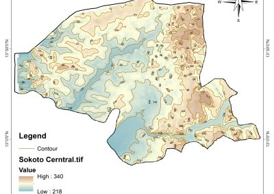
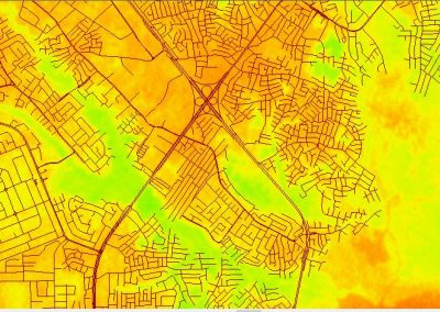
The project’s goal is to describe the general elevation/terrain of the area as well as the sloping trend of the landscape. To do this, a 3D Surface Map of the terrain was developed. The generated surface map is critical for depicting the general elevation trend of the area.
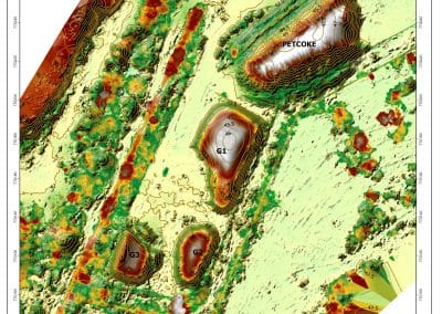
The graphic above demonstrates a variation in elevation levels from high to low. When the point values on the X-axis increase, the slope of the region decreases; as a result, the elevation decreases as we move further along the X-axis.

If we look at the surface map, we see that values closer to the origin have points with a higher elevation than values considerably farther away from the origin. This observation is supported by the use of a simple yet effective instrument known as the Color Scale. The color scale is used to designate a color shade for each point denoting an elevation level. Each color on the color scale represents a different elevation at each position.
Each color value on the scale is a negative value ranging from -27 to -42. -27 denotes the study area’s maximum highest elevation level, whereas -42 represents the study area’s lowest minimum elevation level. We can now distinguish the elevation points in relation to one another using the color scale.