Geophysical/hydrogeophysical Studies for Groundwater Development Project
Learn MoreINTRODUCTION
The importance of groundwater as a supply source to the socio-economic development of a country is tremendous, more so, when it is the only viable source of water in many communities where the development of surface water is not economically feasible. In this 21st century, there is increasing demand for water supply for portable use to achieve maximum human growth. The existing surface water supply scheme has proved inadequate. Overexploitation of surface water is manifested by the lowering of the water table and a regional imbalance associated with the problem of water scarcity for domestic and industrial uses. Hence, detailed identification of the aquifer system is essential for the sustainable development of groundwater in this region.
Considering the limited and winding characteristics of the groundwater reservoirs in the sedimentary terrain, the full benefit of the aquifer system can only be exploited through a well-co-ordinated hydro geophysical and geological investigation program of the prospective area. Geoelectrical techniques are powerful tools and play a vital role in groundwater investigations, particularly in the delineation of the aquifer configuration in complex geological environments. A planned geoelectrical investigation is capable of mapping an aquifer system, clay layers, the depth and thickness of aquifers, and qualitatively estimating local groundwater flow (Fitterman and Stewart, 1986; McNeill, 1987; Olasehinde, 1989) and has been adopted in this study. Thus by combining data on the surface hydrogeological features with subsurface information obtained from geoelectrical investigations, one may define the subsurface features and details of aquifer geometry.
The objectives of the survey include:
- Carrying out a hydrogeologic reconnaissance survey involving rock identification, structural mapping, and static water level measurements from existing wells around the area with a view to locating suitable site(s) for the geophysical survey.
- Delineating near-surface geologic structures such as faults and fractured zones with thick overburden that is favorable to groundwater accumulation and movement.
- Delineating the geoelectric sequence beneath the depth sounding stations and determining the geoelectric parameters.
- Identification of the aquifer units and determination of their depth and lateral extent.
- Evaluating based on the above, the groundwater potential of the study area and the feasibility of development.
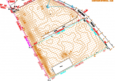
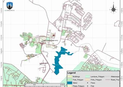
1.1 LOCATION AND ACCESSIBILITY
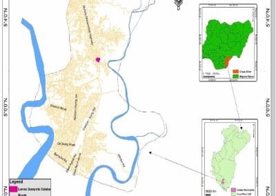
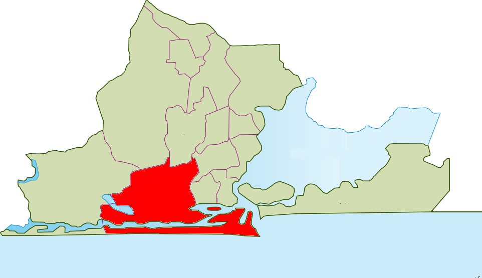
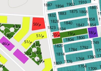
The study area is located at 19b, Shittu Animashaun street, off Jogunomi street, Gbagada Estate, Phase 2, Gbagada, Lagos State. The access roads are motorable and no difficulty is expected to be encountered.
1.2 SCOPE OF WORK
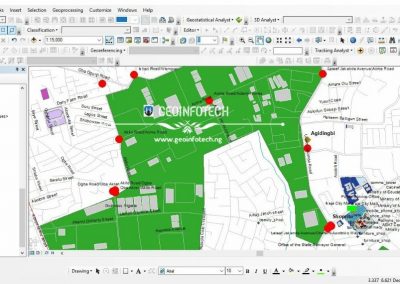
The first stage of this work involves geological and hydrogeologic mapping while the second entails geo-electric investigation (horizontal profiling and vertical electric sounding (VES)).
METHODOLOGY
3.1 PRINCIPLES OF ELECTRICAL RESISTIVITY TECHNIQUE
In the resistivity method, artificially generated electric currents are introduced into the ground and the resulting potential differences are measured at the surface. Deviations from the pattern of potential differences expected from homogenous ground provide information on the form and electrical properties of subsurface inhomogeneities (Keary et al, 2002). The electrical resistivity varies between different geological materials, depending mainly on variations in water contents and dissolved ions in water. Resistivity investigations can thus be used to identify zones with different physical properties that can be related to variations in hydrogeological conditions.
![]()
It should however be pointed out that the electrical resistivity survey simply identifies physical structures which act as conduits for groundwater movement within a rocking body, but does not guarantee the occurrence of water in it, as it could be filled with ore body for example (electrically conductive mineral) or dry fracture. Nonetheless, the electrical resistivity method has an excellent track record when it comes to finding useful quantities of underground water in hard rocks. It should also be stated here that the quality and quantity of underground water depend solely on the rock material with which the rock interacts over the years.
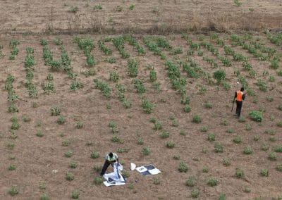
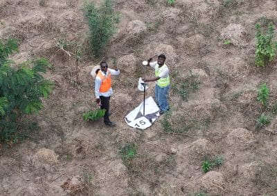
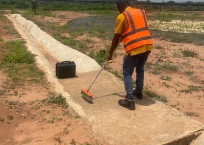
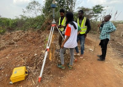
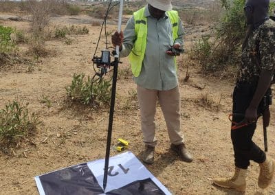
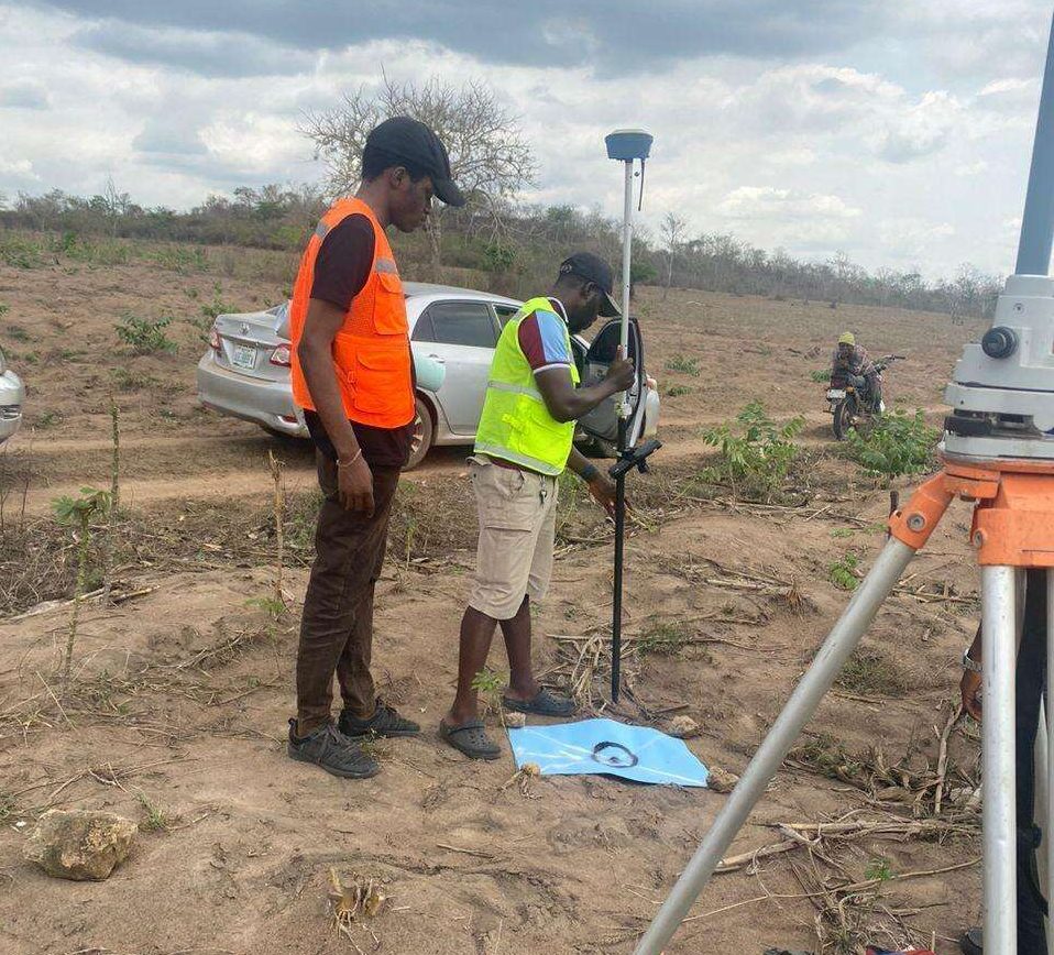
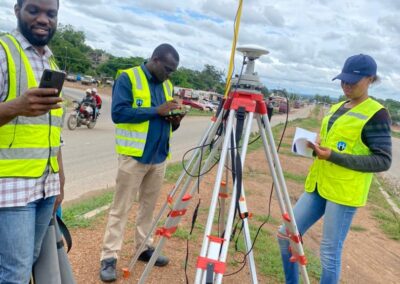
3.2 FIELD TECHNIQUE
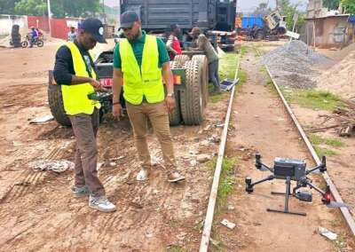
ELECTRICAL RESISTIVITY PROFILING (HP): A one-dimensional (1-D) resistivity model for the subsurface was obtained from electrical profiling surveys. The system employs an array of equally-spaced pre-planted electrodes. This was achieved using the Wenner configuration. The inter-electrode spacing, “a” was set to be 20m and 30m.
VERTICAL ELECTRICAL SOUNDING: VES was done using the Schlumberger electrode configuration. The current and potential electrodes are maintained at the same relative spacing and the whole spread is progressively expanded along a profile. Successive apparent resistivity values are determined at the same center point for increasing values of electrode spacing. The current electrode spacing (AB/2) ranges from 1.0m to 100m.
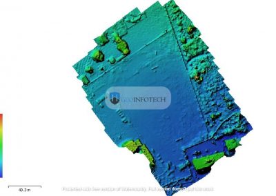
4.0 DATA PROCESSING AND INTERPRETATION
Vertical Electrical Sounding (VES): The sounding curve for each point was obtained by plotting the apparent resistivity on the ordinate against half-current electrode spacing on a bilogarithmic transparent paper. A preliminary interpretation was carried out using partial curve matching involving two-layer master curves and the appropriate auxiliary charts. The layer model thus obtained served as input for an inversion algorithm or computer iterative modeling using the WinResist software.
5.0 CONCLUSION AND RECOMMENDATION
The groundwater potential is expected to be of medium yield. Based on the field observation and the interpretation of the data obtained, borehole drilling within the premise is feasible. The water-bearing horizon (aquifer system) of the study area encompasses the saturated sandstone sequence.
- The depth should be exhausted for the aquifer to be fully exploited,
- To avoid the ingress of contaminants, the borehole should be far away from any septic tank.
- The drillers are advised to gravel pack and grout the hole to avoid groundwater communication with surface water and the blockage of the screen.
- The driller should use his discretion and terminate the hole when the sample obtained indicates enough water.
- The loss casing should be properly fitted to avoid the ingress of surface contaminants.
- Drilling Chemicals should be used to achieve effective drilling.
- A portable water treatment facility is recommended as mild iron concentrations persist