
INTRODUCTION
When working with surveying, geospatial, and engineering drawings, it is often necessary to look beyond the surface of a drawing. You may need to understand the elevation of terrain, examine a road profile, inspect a site, or see how different features relate vertically. This is where the Section Tool in AutoCAD becomes useful.
The section tool allows you to cut through a 3D model or surface and create a view that shows what is happening along a particular line or plane. For surveyors and geospatial professionals, section views can help with terrain analysis, site investigation, road design, profiles, and engineering documentation.
WHAT IS THE SECTION TOOL IN AutoCAD
The Section Tool creates a cutting plane through a 3D object or model. Instead of viewing the entire object from the outside, you can use the section to examine its internal structure or create a cross-sectional representation.
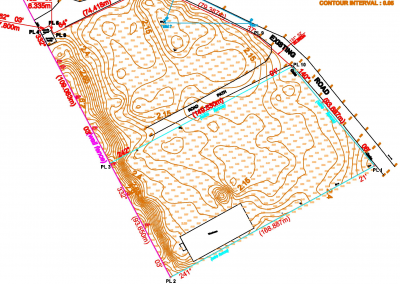
For example, imagine you have a 3D representation of a surveyed site. A section taken across the site can help you understand how the ground rises and falls along that particular direction.
In AutoCAD, the SECTIONPLANE command is used to create an interactive section plane through 3D objects.
HOW TO USE THE SECTION TOOL IN AutoCAD
STEP 1: Open Your 3D Drawing
Start AutoCAD and open the drawing containing the 3D data or model you want to examine.
For geospatial and surveying work, this could be a 3D site model, terrain representation, or other three-dimensional drawing.
STEP 2: Activate the Section Plane
On the command line, type: SECTIONPLANE and press Enter.
AutoCAD will prompt you to define the section plane. You can also access the section plane tools through the AutoCAD interface.
STEP 3: Define the Section Direction
Choose how you want to create your section. You can define the section by selecting a face, specifying points, or choosing an orthographic direction such as Top, Bottom, Front, Back, Left, or Right.
For surveying and geospatial applications, the direction you choose is important because it determines which part of your terrain or model you are examining.
STEP 4: Position the Section Plane
Click to position the section plane across your model.
For example, if you have a 3D representation of a surveyed site, you could position the section plane across a particular road alignment or area of interest.
You can then move the plane through the model to examine different locations.
STEP 5: Examine the Section
Once the section plane is active, AutoCAD allows you to see the portion of the model intersected by the plane.
This can help you identify changes in elevation, terrain form, internal components, or relationships between different features.
For surveyors, this type of view can be useful when examining ground profiles and site conditions.
STEP 6: Adjust the Section
You can move and adjust the section plane until you obtain the exact view you need.
Changing the position of the section allows you to examine different parts of your model without having to create a completely new drawing.
STEP 7: Create a Section for Documentation
Once you have the required section, you can use it as part of your technical documentation.
Depending on the project, the section can be incorporated into drawings showing terrain profiles, site conditions, road alignments, or engineering features.
HOW SURVEYORS CAN USE SECTION VIEWS
Section views have several applications in surveying and geospatial work.
1. Terrain and Elevation
A section through a terrain model can show how elevation changes along a particular direction. This can help you understand slopes, high points, low points, and changes in terrain.
2. Road and Route Analysis
Sections can be used to examine terrain along a proposed road or alignment. This provides useful information about how the road interacts with the existing ground.
3. Site Investigation
For a surveyed development site, sections can provide another way of understanding the relationship between different ground elevations and site features.
4. Engineering Projects
Survey data often provides the foundation for engineering design. Section drawings can help engineers understand existing site conditions before developing roads, drainage systems, buildings, and other infrastructure.
CONCLUSION
At GeoInfoAcademy, AutoCAD training can be approached from a practical geospatial and surveying perspective. Instead of learning commands in isolation, learners can develop skills that connect CAD drafting with real-world surveying and mapping workflows.
This includes understanding how AutoCAD can be used to work with survey data, coordinates, site plans, terrain information, boundaries, and other geospatial features.
For surveyors, GIS professionals, engineering students, and anyone working with spatial data, this practical approach helps turn AutoCAD knowledge into a useful professional skill.
Learn with Geoinfoacademy today.