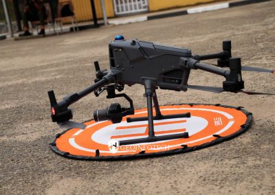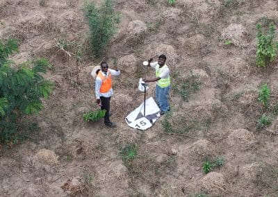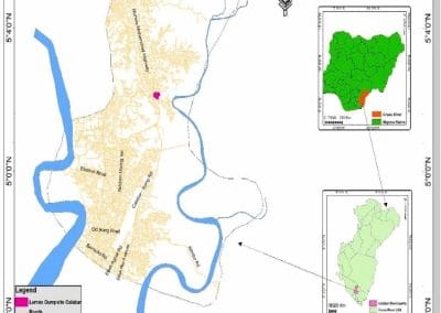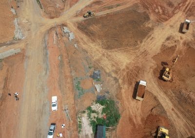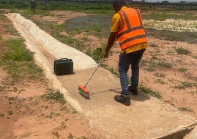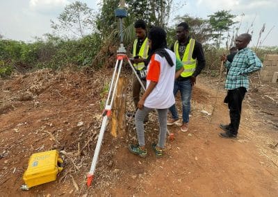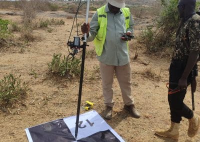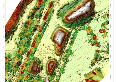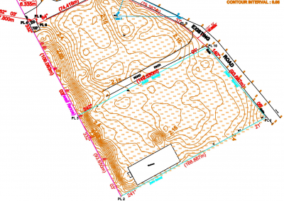

When working with sensors in engineering, surveying, mapping, manufacturing, or industrial design, having the right mounting arrangement is essential for accurate positioning and reliable operation. A CAD-designed structure used to position a sensor correctly within a larger system.
Therefore, for professionals using AutoCAD to design, modify, or document sensor mounting solutions, understanding the purpose, design considerations, and applications of sensor mounts can make the design process much easier.
What Is an AutoCAD Sensor Mount?
An AutoCAD sensor mount is a sensor mounting design created or documented using AutoCAD. For example, it may represent a physical bracket, holder, support structure, adapter, or mounting plate designed to secure a sensor in a specific position.
AutoCAD allows designers to create accurate 2D drawings and 3D models of these components. Additionally, designers can incorporate dimensions, holes, mounting points, angles, clearances, and connection details into the design before manufacturing or installation.
Why Is Sensor Mount Design Important?
Sensors often need to remain in a precise position to collect reliable measurements.For this reason, even a small change in orientation or location can affect the quality of the data produced by a sensor.
A properly designed mount can help with:
- Accurate sensor positioning
- Stable installation
- Correct sensor orientation
- Protection against movement and vibration
- Easier installation and maintenance
- Compatibility with existing equipment
- Accurate manufacturing and fabrication
Furthermore, these considerations are particularly important in engineering and surveying applications because professionals may use sensor data for measurements, mapping, monitoring, or automated systems.
AutoCAD sensor mount: Common Types
There is no single type of sensor mount. Instead, the appropriate design depends on the sensor, equipment, and environment where engineers or designers will install it.
- Fixed Sensor Mounts
Fixed mounts hold a sensor in a predetermined position. Therefore, they are suitable for applications where the sensor does not need regular adjustment after installation.
- Adjustable Sensor Mounts
Adjustable mounts allow the sensor to be moved or rotated. As a result, these mounts are useful when installers need to align the sensor precisely during installation.
- Bracket Mounts
For example, engineers commonly use bracket-style mounts to attach sensors to walls, poles, machinery, frames, or other structures.
- Custom Sensor Mounts
Some applications require a completely custom mounting solution. AutoCAD can be used to develop a detailed design based on the dimensions and mounting requirements of the specific sensor.
Designing an AutoCAD sensor mount
Designing a sensor mount in AutoCAD normally starts with understanding the physical requirements of the sensor and its installation environment.
Important information may include the sensor’s:
- Overall dimensions\
- Weight
- Mounting-hole pattern
- Required orientation
- Connection points
- Operating environment
- Cable or connector clearance
- Required adjustment range
After these specifications are established, the designer can create the mounting component in AutoCAD and add the necessary dimensions and construction details.
Key Design Considerations
A good sensor mount should do more than simply hold the sensor in place. The design should consider how the mount will perform during actual use.
Accuracy and Alignment
The mount should position the sensor accurately according to the requirements of the application. Incorrect alignment can affect measurements and system performance.
Material and Strength
The material selected should be strong enough to support the sensor and withstand the expected operating conditions.
Vibration
If the sensor is installed on machinery, vehicles, drones, or other equipment that experiences vibration, the mounting design should account for movement and vibration.
Accessibility
The sensor should remain accessible for maintenance, replacement, calibration, or inspection where necessary.
Clearance
Adequate space should be provided around the sensor, connectors and cables. A mount that fits the sensor but restricts its connections may create installation problems.
How AutoCAD Helps with Sensor Mount Design
AutoCAD provides several tools that can make sensor-mount development more precise and efficient.
Designers can use:
- 2D drafting tools for technical drawings
- 3D modelling for physical visualization
- Dimensioning tools for accurate measurements
- Layers for organizing design information
- Blocks and reusable components
- Constraints for maintaining geometric relationships
- Section views for examining internal details
- Layouts for preparing drawings for printing or sharing
A 3D model can also help designers identify potential interference or clearance problems before a physical component is manufactured.
From AutoCAD Design to Fabrication
After completing the sensor mount design, the drawing can be prepared for fabrication. Depending on the manufacturing method, the design may be used to communicate dimensions and specifications to a fabricator or exported into an appropriate file format for downstream manufacturing workflows.
Before fabrication, it is important to verify:
- All critical dimensions.
- Mounting-hole locations.
- Sensor orientation.
- Material specifications.
- Fastener requirements.
- Required clearances.
- Compatibility with the equipment where the mount will be installed.
Applications of Sensor Mounts
Sensor mounts can be used across many industries and applications.
Examples include:
- Surveying equipment
- Industrial monitoring
- Robotics
- Manufacturing machinery
- Agricultural equipment
- Drones and UAV systems
- Vehicle-mounted sensors
- Environmental monitoring
- Construction equipment
- Research and testing equipment
The actual mount will vary considerably depending on the sensor and application.
Common Mistakes to Avoid
When designing a sensor mount in AutoCAD, seemingly small mistakes can create problems during installation or operation.
Common issues include:
- Using incorrect sensor dimensions
- Forgetting cable clearance
- Poor mounting-hole placement
- Insufficient structural strength
- Ignoring vibration
- Failing to account for installation tools
- Designing without considering maintenance access
- Omitting important dimensions from technical drawings
Checking the design carefully before fabrication can reduce costly modifications later.
Conclusion
An AutoCAD sensor mount provides a practical way to design and document the component used to position and secure a sensor. AutoCAD’s drafting and 3D modelling capabilities allow engineers, designers, surveyors and other professionals to develop accurate mounting solutions before fabrication or installation.
Whether you need a simple fixed bracket, an adjustable holder or a completely custom mounting system, starting with accurate sensor specifications and considering alignment, strength, clearance, vibration and maintenance requirements will help produce a more reliable design.
Ready to start learning Everything You Need to Know About AutoCAD Sensor Mount? Explore AutoCAD training with Geoinfoacademy and begin building practical CAD skills today.
Apply now: https://geoinfotech.ng/training-geoinfotech-training-new/