
Introduction
Civil engineering and surveying projects often involve terrain, elevations, alignments, profiles, corridors, and other types of spatial data. Managing these elements requires tools that go beyond basic 2D drafting.
AutoCAD Civil 3D is designed to support these types of civil engineering and infrastructure workflows. It combines familiar AutoCAD drafting capabilities with specialized tools for working with surfaces, terrain models, alignments, profiles, corridors, and other civil design elements.
Whether you are a beginner, surveyor, civil engineering student, or CAD professional, understanding the basics of Civil 3D can give you a stronger foundation for working on real-world projects.
What is autocad civil 3d?
AutoCAD Civil 3D is a civil engineering design and documentation software developed by Autodesk. It provides tools for creating and managing civil infrastructure designs while using a dynamic model-based approach.
Unlike basic CAD drafting, Civil 3D can connect related design elements. For example, changes made to a surface can affect other objects that depend on that surface.
Civil 3D is commonly used for tasks involving:
- Land surveying
- Topographic mapping
- Surface modelling
- Road design
- Site development
- Grading
- Drainage design
- Alignments and profiles
- Corridor modelling
- Construction documentation
This makes it particularly useful for projects where terrain and engineering design need to work together.
Are AutoCAD and Civil 3D the Same?
AutoCAD and Civil 3D are related, but they are not the same software.
AutoCAD is a general-purpose CAD application used for creating 2D drawings and 3D designs across many industries.
Civil 3D builds on the AutoCAD environment and adds specialised tools for civil engineering and surveying workflows.
For example, a user can create basic lines, circles, polylines, layers, and annotations in both environments. However, Civil 3D also provides specialised objects and tools for working with:
- Existing ground surfaces
- Profiles
- Alignments
- Corridors
- Parcels
- Pipe networks
- Survey data
- Grading
Therefore, someone who already understands AutoCAD will have a useful foundation when learning Civil 3D, but there are additional concepts and workflows to understand.
What Can You Do With Civil 3D?
Civil 3D can be used throughout different stages of a civil engineering or surveying project.
Survey and Topographic Data
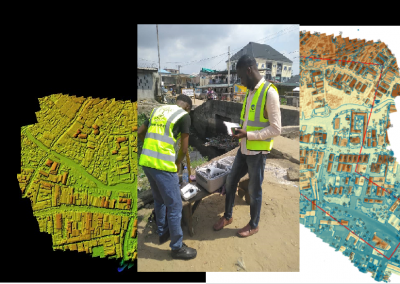
Survey observations and point data can be imported and organised to represent existing site conditions.
Surface Modelling
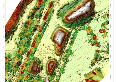
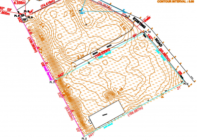
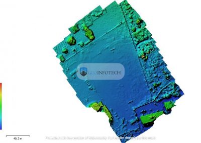
Survey points, contours, breaklines, and other data can be used to create a digital representation of the terrain.
Road Design
Civil 3D provides tools for creating horizontal alignments, vertical profiles, assemblies, and corridors.
Site Development
Designers can use surfaces, grading tools, parcels, and other features to develop site plans.
Documentation
Plans, profiles, sections, labels, and other drawing components can be prepared for project documentation.
How to display coordinates in autocad
Coordinates are important when working with survey and engineering drawings. They allow you to identify the precise position of points within your drawing.
One simple way to check the coordinates of a location is to move the cursor around the drawing area and observe the coordinate information displayed in the AutoCAD interface.
You can also use commands and inquiry tools to obtain the coordinates of specific points.
For a selected point or object, tools such as ID can provide the X, Y, and, where applicable, Z coordinate values.
When working with Civil 3D, coordinate information becomes particularly useful when handling survey points, surfaces, alignments, and geospatial data.
Why Coordinate Systems Matter
Coordinates are only useful when you understand the coordinate system being used.
A survey project may use a projected coordinate system rather than simple local drawing coordinates. Using the wrong coordinate system can cause data to appear in the wrong location.
Therefore, always confirm the coordinate reference system and units before importing survey or GIS data into a Civil 3D project.
how to create a surface in autocad civil 3d
A surface is one of the most important objects in Civil 3D. It can represent existing terrain or a proposed design.
A surface can be created from different types of source data, including:
- Survey points
- Point files
- Contours
- Breaklines
- Point groups
- Other Civil 3D objects
The general workflow involves creating a surface and then adding the appropriate source data to it.
Step 1: Create a New Surface
From the Toolspace panel, navigate to the Prospector tab and locate the Surfaces collection.
Create a new surface and choose the appropriate surface type and style.
Step 2: Add Source Data
After creating the surface, add the available terrain information.
For example, if you have survey points, you can add the relevant point group to the surface.
If contour data is available, you can add the contours as surface data.
Step 3: Check the Surface
Once the data has been added, inspect the resulting surface.
You can display features such as:
- Contours
- TIN lines
- Points
- Elevation ranges
- Slope information
Checking the surface is important because incorrect or incomplete source data can produce an inaccurate terrain model.
Step 4: Analyse the Surface
Civil 3D provides several tools for analysing a surface.
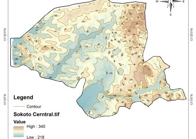
You can examine elevation, slope, contours, and other terrain characteristics. These analyses can help you understand the existing conditions before moving to the design stage.
Understanding TIN Surfaces
Civil 3D commonly represents terrain using a Triangulated Irregular Network (TIN).
A TIN surface uses interconnected triangles to represent variations in terrain elevation. The triangles are created from available elevation data and other surface information.
The quality of the resulting surface depends heavily on the quality and distribution of the source data.
For this reason, survey points and breaklines should be checked carefully before relying on the final surface for design decisions.
Working With Alignments and Profiles
Alignments are useful when designing linear features such as roads, routes, and other infrastructure.
An alignment represents the horizontal path of a proposed or existing feature.
Profiles, on the other hand, represent elevation changes along an alignment.
Together, alignments and profiles allow designers to examine both the horizontal and vertical aspects of a project.
These tools are particularly important in road and infrastructure design.
What Are Civil 3D Corridors?
A corridor is a model used to represent a linear infrastructure design, such as a road.
Civil 3D corridors can combine elements such as:
- Alignments
- Profiles
- Assemblies
- Surfaces
- Design parameters
This allows a proposed road or similar feature to be modelled in three dimensions.
Corridor models can also support the production of plan, profile, and section information needed for project documentation.
Common Civil 3D Beginner Mistakes
Civil 3D contains many interconnected tools, so beginners can encounter problems when they focus only on individual commands.
Common mistakes include:
- Using the wrong coordinate system
- Importing incorrect survey data
- Creating surfaces from incomplete information
- Ignoring units
- Failing to check surface elevations
- Poor layer organisation
- Using unsuitable surface styles
- Not understanding the relationship between Civil 3D objects
A good learning approach is to start with small projects and gradually introduce more advanced tools.
How to Start Learning Civil 3D
If you already know basic AutoCAD, begin by learning how Civil 3D manages specialised objects.
A practical learning sequence is:
- Review basic AutoCAD drafting and editing.
- Learn the Civil 3D interface and Toolspace.
- Import and manage survey points.
- Create and analyse surfaces.
- Work with alignments and profiles.
- Learn basic grading and corridor concepts.
- Practise creating plans and project documentation.
Working through a small survey or road-design project can help you understand how these tools work together.
Conclusion
AutoCAD Civil 3D provides specialised tools for civil engineering, surveying, infrastructure design, and terrain-based projects. While it shares the familiar AutoCAD environment, it offers additional functionality for working with surfaces, coordinates, alignments, profiles, corridors, and other civil design elements.
Understanding what AutoCAD Civil 3D is, how it differs from standard AutoCAD, how to work with coordinates, and how to create a surface provides a strong starting point for beginners.
With regular practice and real project exercises, Civil 3D can become a valuable tool for managing survey information and developing accurate civil engineering designs.
At Geoinfoacademy, we help learners build practical AutoCAD, Civil 3D, surveying, and technical drawing skills through structured, industry-focused training. Whether you are learning how to work with coordinates, create terrain surfaces, or develop civil design workflows, practical training can help you build the confidence needed to apply these skills to real projects.
Apply now: https://geoinfotech.ng/training-geoinfotech-training-new/