
Introduction
Land surveying involves collecting accurate information about the position, shape, elevation, and boundaries of features on the Earth’s surface. However, collecting survey measurements in the field is only part of the job. Surveyors must also process, organize, analyze, and present that information in a clear technical drawing. This is where AutoCAD becomes particularly useful.
AutoCAD is a computer-aided design (CAD) software developed by Autodesk and is widely used for creating precise 2D drawings and 3D models. Although it is used across many industries, its drafting and editing capabilities make it a valuable tool for land surveying projects.
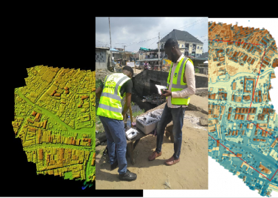
AutoCAD can be used to transform field observations and coordinate data into professional survey plans. For example, data collected with a total station, GNSS receiver, or other surveying equipment can eventually be represented as points, lines, boundaries, contours, buildings, roads, and other features within an AutoCAD drawing.
For instance, a surveyor carrying out a boundary survey may collect coordinates for boundary points in the field. Those coordinates can then be plotted in AutoCAD and connected to create the surveyed property boundary.
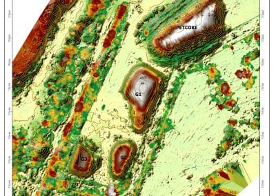
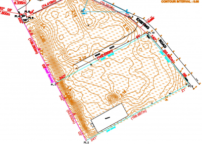
Similarly, a topographical survey may contain hundreds or thousands of points representing terrain and physical features. These points can form the basis for a detailed site plan containing roads, buildings, drainage channels, fences, vegetation, spot elevations, and other surveyed features.
Therefore, learning how to use AutoCAD for land surveying can help surveyors move efficiently from field data collection to a properly organized survey drawing.
Why Do Surveyors Use AutoCAD for Surveying Projects?
There are several reasons AutoCAD remains useful in surveying workflows.
1. Precision
Surveying requires accurate representation of measured positions and distances. AutoCAD allows users to work with numerical coordinates and precise dimensions rather than relying on freehand drawing.
2. Efficient Editing
Survey drawings often require revisions. Consequently, a surveyor can modify, move, copy, trim, extend, or delete objects without having to redraw an entire plan.
3. Professional Survey Plans
AutoCAD provides tools for creating organized technical drawings containing boundaries, dimensions, labels, north arrows, symbols, title blocks, and other essential information.
4. Compatibility
AutoCAD’s DWG format is widely used in engineering, surveying, architecture, and construction workflows. Therefore, survey drawings can be shared and incorporated into other design processes.
5. Organization
Through layers, blocks, annotation tools, and other drafting features, surveyors can organize different types of information within a single drawing.
AutoCAD Surveying Tutorial: A Basic Surveying Workflow
If you are searching for an AutoCAD surveying tutorial, it is useful to understand the complete workflow rather than learning individual commands in isolation.
A typical workflow can be divided into several stages.
1: Collect Survey Data
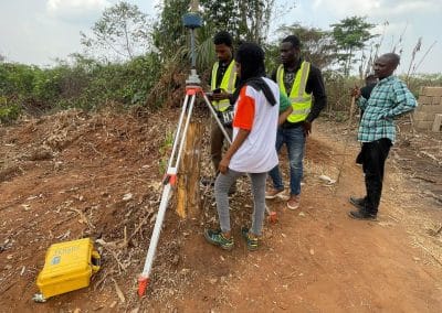
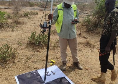
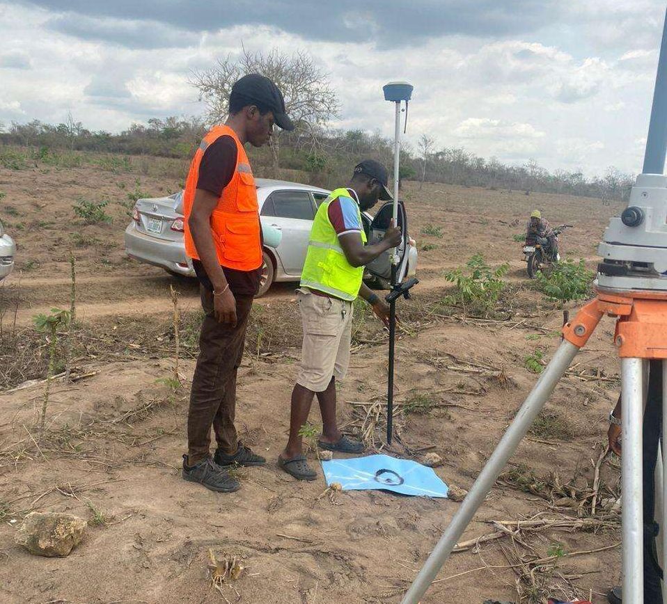
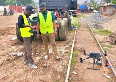
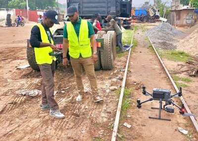
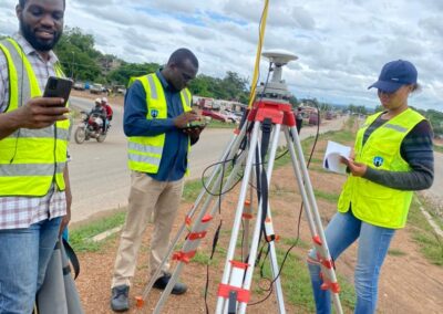
The process begins in the field. Depending on the project, surveyors may use total stations, GNSS receivers, digital levels, drones, or other surveying equipment.
The resulting observations may include coordinates, elevations, point descriptions, distances, and other information.
2: Prepare the Survey Data
Before importing or plotting the information, check that the coordinate data is properly organized.
For example, a coordinate file may contain:
- Point number,
- Eastings,
- Northings,
- Elevation, and
- Point description.
It is important to verify that the coordinate order and units are correct before proceeding.
3: Establish the Drawing Environment
Create a new AutoCAD drawing and establish appropriate drawing units.
For a surveying project, the units should correspond with the survey data. For example, if the field coordinates are measured in meters, the drawing should be appropriately configured for metric work.
Next, create layers for major feature categories such as:
- Boundary
- Buildings
- Roads
- Drainage
- Spot elevations
- Vegetation
- Text
- Dimensions
- Existing features
- Proposed features
4: Plot the Survey Coordinates
Once the data is properly prepared, the survey points can be represented in the drawing.
The points provide the spatial framework from which other features can be created. For example, boundary points can be connected to form a parcel boundary, while points representing a building can be connected to reproduce its footprint.
5: Connect and Draft Features
After plotting the points, use appropriate AutoCAD commands to create the surveyed features.
For example, LINE or PLINE can be used to connect boundary points, while text and annotation tools can be used to identify features.
6: Add Dimensions and Annotations
A professional survey plan should communicate information clearly. Therefore, add relevant dimensions, bearings, distances, elevations, point numbers, feature descriptions, and other required annotations.
7: Review the Drawing
Before producing the final plan, carefully check the drawing for errors.
Verify the:
- Coordinates
- Distances
- Bearings
- Labels
- Boundary connections
- Units
- Layer organization
- Drawing scale
- Missing features
Finally, prepare the drawing for plotting or digital delivery.
Creating Survey Plans and Site Drawings
After the survey data has been plotted, AutoCAD can be used to produce different types of survey drawings.
Boundary Survey Plans
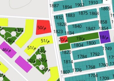
Boundary surveys can show property corners, parcel boundaries, dimensions, bearings, adjoining properties, and other relevant information.
Topographical Survey Plans
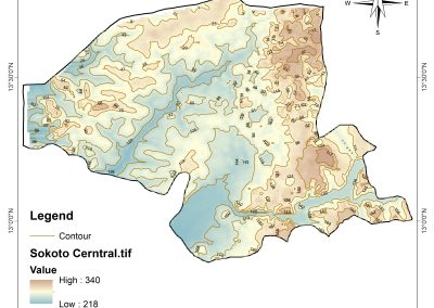
Topographical drawings can represent existing ground conditions and physical features such as buildings, roads, drainage, vegetation, utility features, and spot elevations.
Site Plans
Survey data can also provide the foundation for site plans used in construction and development projects.
As-Built Drawings
After construction, survey measurements can be drafted in AutoCAD to document the actual location of constructed features.
Consequently, the same basic AutoCAD skills can support several stages of a land development project.
AutoCAD and Coordinate Systems in Land Surveying
Coordinates are fundamental to modern land surveying. A surveyor may work with local coordinates, projected coordinates, or another established reference system depending on the project requirements.
AutoCAD can represent coordinate values accurately; however, the software itself does not automatically guarantee that the coordinates have been assigned the correct real-world reference.
For this reason, surveyors should understand the coordinate reference system used for their project before drafting. For example, confusing Easting and Northing, using the wrong units, or applying an incorrect coordinate transformation can result in a drawing that is incorrectly positioned.
Therefore, coordinate management should be treated as an important part of quality control rather than simply an input step.
Applications of AutoCAD in Land Surveying
AutoCAD can support numerous surveying activities, including:
- Boundary and cadastral survey drafting
- Topographical survey plans
- Engineering survey drawings
- Construction site surveys
- Road and route survey drawings
- As-built surveys
- Subdivision plans
- Property development plans
- Utility mapping
- Setting-out drawings
- Existing-condition drawings
Furthermore, AutoCAD can work alongside other surveying and geospatial software. A surveyor may collect data using GNSS or a total station, process it using dedicated survey software, and then use AutoCAD to create or refine the final drawing.
Common Mistakes to Avoid
Although AutoCAD is powerful, mistakes can occur when surveyors do not properly manage their data.
Some common problems include: Incorrect Units, Reversed Coordinates, Poor Layer Management, Inaccurate Manual Drafting, Ignoring Coordinate Reference Systems, Inadequate Quality Control.
Conclusion
AutoCAD plays an important role in transforming land surveying data into clear, accurate, and professional technical drawings. From plotting coordinates and drafting boundaries to producing topographical plans and preparing construction drawings, the software provides surveyors with a flexible environment for managing the graphical side of their projects. An effective AutoCAD surveying tutorial should connect individual commands to real surveying workflows. Instead of learning LINE, OFFSET, TRIM, or DIMENSION as isolated commands, learners should understand how those tools contribute to producing an accurate and professional survey plan.
At Geoinfoacademy, learners can build practical AutoCAD skills through structured training and real-world applications, developing the confidence needed to apply CAD techniques to surveying, engineering, construction, and other geospatial projects.
Apply now: https://geoinfotech.ng/training-geoinfotech-training-new/