- Introduction
Surveying has undergone a profound transformation over the past three decades. Optical theodolites and steel tapes have largely given way to electronic Total Stations capable of storing thousands of points, while GNSS receivers now routinely deliver centimetre-level positional accuracy in real time using RTK (Real-Time Kinematic) correction networks. Modern surveying operations generate large volumes of spatial data from two primary. Global Navigation Satellite System (GNSS) receivers and Total Station (TS) instruments. Translating this field-collected data into accurate, production-ready AutoCAD drawings is a critical step in nearly every land survey, civil engineering, and construction staking workflow. Despite these advances, the link between field instrument and drawing office remains a potential bottleneck if data transfer is not handled systematically.
AutoCAD and its vertical derivative AutoCAD Civil 3D are the dominant CAD platforms in the surveying and civil engineering disciplines. Both platforms offer rich tools for importing coordinate data, but the process involves several decisions around file formats, coordinate systems, and point stylisation that can significantly affect the quality of the final deliverable. This write-up addresses the principal file formats used to export data from GNSS receivers and Total Stations, describe the correct process for importing point coordinate files into AutoCAD and Civil 3D, explain coordinate transformation concepts and how to apply datum shifts before importing. It also, demonstrate the creation and management of COGO (Coordinate Geometry) points.
Present a recommended step-by-step workflow from field collection to finished drawing.
Highlight common errors and their remedies.
- Field Instruments and Data Output
There are different instruments surveying and outputs when importing GNSS and total station data into AutoCAD.

2.1 Total Stations
A Total Station is an electro-optical surveying instrument that combines a theodolite for measuring horizontal and vertical angles with an Electronic Distance Meter (EDM) for measuring slope distances. Modern instruments compute and store three-dimensional coordinates of observed points relative to a known instrument station. Data is stored internally on the instrument memory or on a data collector (field computer) running survey software such as Trimble Access, Leica Captivate, Topcon Magnet Field, or Carlson SurvPC. When a survey session is complete, the operator downloads raw or processed observations to a PC. Total station export formats are shown in Table 1.
Table 1: Common Total Station Export Formats
| Format | Extension | Description | Common Source |
| CSV / ASCII | .csv, .txt | Plain-text point coordinates. Most universal transfer format. | All manufacturers |
| SDR (Sokkia Raw) | .sdr | Binary observation format for Sokkia instruments. | Sokkia / Topcon |
| RAW (Nikon) | .raw | ASCII observation file from Nikon instruments. | Nikon |
| JXL (Trimble) | .jxl | XML-based job file from Trimble data collectors. | Trimble |
| GSI (Leica) | .gsi | Leica Geosystems format; ASCII fixed-width records. | Leica |
| RW5 (Carlson) | .rw5 | Field data reduction format used by Carlson Survey. | Carlson / Generic |
| DXF | .dxf | AutoCAD interchange; may be exported directly from some controllers. | Multiple |
| LandXML | .xml | Open standard; widely supported for point and alignment data. | Multiple |
2.2 GNSS Receivers
GNSS receivers track signals from multiple satellite constellations (GPS, GLONASS, Galileo, BeiDou) to compute three-dimensional positions. For precision survey work, RTK receivers use a base station or a continuously operating reference station (CORS) network to achieve horizontal accuracies typically better than 20 mm and vertical accuracies better than 40 mm. GNSS positions are natively computed in an Earth-Centred Earth-Fixed (ECEF) reference frame and are most commonly reported in geodetic latitude, longitude, and ellipsoidal height relative to a standard ellipsoid such as WGS84. Before import into a project CAD file, these coordinates must usually be projected into a local grid coordinate system. Some export formats of GNSS are depicted in Table 2
Table 2: Common GNSS Export Formats
| Format | Notes |
| CSV (Lat/Long or Easting/Northing) | Most common; requires CRS metadata to be recorded separately. |
| RINEX | Receiver-Independent Exchange format for raw observation data; requires post-processing. |
| LandXML | Stores points with full coordinate system metadata; preferred for Civil 3D. |
| Shapefile (.shp) | GIS format; readable in Civil 3D via Map 3D functionality. |
| JXL / JOB (Trimble) | Proprietary job file; converted via Trimble Business Center. |
| T02 (Trimble) | Raw GNSS observation file; requires Trimble Business Center for conversion. |
- Coordinate Reference Systems and Transformations
In surveying there is need for keen attention to coordinate reference system and transformation as they are essential in data processing and final outputs.

3.1 Why Coordinate Transformation Matters
One of the most consequential steps in moving from field data to a CAD drawing is ensuring that all data is expressed in a consistent, project-appropriate coordinate reference system (CRS). Mixing coordinate systems: for example, importing RTK GNSS data in geographic coordinates (degrees) without projecting them, or importing Total Station data referenced to an arbitrary local grid alongside GNSS data in a state plane system will produce drawings where features do not align correctly.
A full Coordinate Reference System Components (CRS) definition has three components:
- Datum: the reference ellipsoid and its orientation (e.g., WGS84, NAD83, GDA2020),
- Projection: the mathematical transformation from the curved ellipsoid surface to a flat plane (e.g., UTM, State Plane, MGA), and
- Vertical datum: the reference surface for height values (e.g., EGM2008 geoid, local benchmark).
The above three components comprise the key concept of CRS
3.2 Transforming GNSS Data to a Local Grid
Most design and construction projects use a projected coordinate system. The surveyor must apply the appropriate projection transformation before importing GNSS data into AutoCAD. The typical workflow include:
- Collection of RTK GNSS positions in WGS84 geographic coordinates (or allow the data collector software to project in real-time using an on-board CRS library such as PROJ).
- In office processing software (Trimble Business Center, Leica Infinity, StarNet, etc.), apply the correct map projection to obtain grid Easting (E), Northing (N), and elevation (Z) values.
- If a local site calibration or site transformation has been established to reconcile GNSS coordinates with existing survey control, apply those transformation parameters.
- Export the processed point list as a CSV or LandXML file in the project CRS before importing into AutoCAD.
3.3 Civil 3D Coordinate System Support
AutoCAD Civil 3D maintains an internal coordinate system for the drawing. Before importing any survey data, set the drawing coordinate system by navigating to Settings > Drawing Settings > Units and Zone tab. Selecting the correct CRS enables Civil 3D to perform on-the-fly re-projection of incoming data and to correctly reference imagery or other spatial layers.
Civil 3D uses the Autodesk® coordinate system library (derived from EPSG and PROJ databases) and supports hundreds of national and international projections. Always confirm the EPSG code for your project CRS before beginning work.
- Preparing Data for Import
4.1 Structuring a Point Data File
Regardless of the source instrument, the most universally accepted import format for basic point data in AutoCAD is a plain-text CSV or space-delimited ASCII file. The required fields and their common column orders are shown in Table 3.
Table 3: Required Fields and their common Column Orders
| Column Order | Field | Example Value | Notes |
| 1 | Point Number | 1001 | Must be unique within the import file. |
| 2 | Northing (Y) | 5423817.342 | Metres or feet depending on project units. |
| 3 | Easting (X) | 312456.789 | Metres or feet depending on project units. |
| 4 | Elevation (Z) | 48.325 | Orthometric or ellipsoidal height. |
| 5 | Point Description | TOPO_KERB | Feature code; used for symbol assignment. |
AutoCAD Civil 3D refers to this arrangement as the PNEZD format (Point, Northing, Easting, Elevation, Description). An alternative arrangement: PENZD swaps the Easting and Northing columns. The operator must confirm the column order before import to avoid transposing X and Y coordinates, a common and costly error.
4.2 Data Cleaning
Before importing, open the point file in a text editor or spreadsheet application and verify the following:
- No duplicate point numbers exist. Duplicate numbers will cause import conflicts or silent overwriting.
- No missing or null coordinate values are present. A single blank cell can cause entire rows to be skipped.
- Decimal separators are consistent with the system locale (period vs. comma). Some European systems use commas as decimal separators, which conflicts with CSV comma delimiters.
- Description strings do not contain commas, which would break CSV column parsing. Enclose descriptions in double quotes if necessary.
- The first row is either a valid data row or a clearly identifiable header row that can be skipped during import.
- Elevation values are in the correct vertical unit. Mixing metric and imperial elevations in the same file is a frequent error when combining Total Station and GNSS data sets.

- Importing Points into AutoCAD Civil 3D
5.1 Overview of COGO Points
In AutoCAD Civil 3D, survey point data is stored as COGO (Coordinate Geometry) Points. COGO points are first-class Civil 3D objects: they have a defined position in 3D space, a unique point number, an elevation, and a description. They are organised into Point Groups and can be styled independently of the base AutoCAD layer system. The distinction between COGO points and simple AutoCAD block insertions is important. The COGO points are managed by the Civil 3D data model and participate in surface creation, label expression, and other engineering workflows.
5.2 Step-by-Step Import Procedure
Step 1: Set Drawing Units and Coordinate System
Before importing any data, navigate to Settings > Drawing Settings. On the Drawing Units tab, confirm that the linear unit (metre or foot) matches the project CRS. On the Units and Zone tab, select the coordinate zone. Click OK to apply.
Step 2: Open the Points Collection Manager
In the Toolspace > Prospector tab, right-click on the Points collection and select Create Points — from File. Alternatively, use the ribbon: Home > Create Ground Data > Points > Import Points.
Step 3: Configure the Import Format
In the Import Points dialog, click the Format drop-down. For a standard CSV file with the column order Point Number, Northing, Easting, Elevation, Description, select PNEZD (Comma Delimited). If your file uses a different column order, click the Format Manager button to create a custom format definition by mapping columns to fields.
Step 4: Select Source File and Point Group
Browse to the source CSV or TXT file. In the ‘Add Points to Point Group’ field, either select an existing Point Group or type a new name. Creating descriptive Point Groups (e.g., ‘TS_Topo_Survey_2025-03’ or ‘GNSS_Control_Points’) is essential for managing large point sets and for controlling layer visibility and label styles.
Step 5: Execute the Import
Click OK. Civil 3D will read the file and create COGO points. If any errors are encountered (duplicate point numbers, invalid coordinates) the Points Import Log will list the affected records. Review the log carefully before proceeding.
Step 6: Verify Point Positions
After import, zoom to the extents of the drawing (type Z then E at the command line). Visually inspect the point cloud against any known control or reference geometry. Use the INQUIRY command or hover over individual COGO points to check individual coordinate values against the source file.

DCIM102MEDIADJI_0367.JPG
Pro Tip: Using the AECC_POINTS Layer the following are essential:
Civil 3D automatically places COGO points on a layer called AECC_POINTS. Do not attempt to control point visibility by turning off this layer: use Point Group display overrides instead. Each Point Group can have its own Point Style and Point Label Style, giving fine-grained control over symbol type, size, elevation label, and description label for each category of point.
- Importing Data into Standard AutoCAD (Without Civil 3D)
6.1 Using the SCRIPT Command
For users without Civil 3D, point data can be imported into standard AutoCAD using a script file. A script file is a plain-text file with the extension .scr that contains a sequence of AutoCAD commands and coordinate values. Each point is inserted as a POINT entity or as a BLOCK (symbol) at specified coordinates.
A simple script to insert a point at known coordinates looks like this:
| ; AutoCAD Script — Insert POINT entities from coordinate list POINT 312456.789,5423817.342,48.325 POINT 312461.112,5423820.005,48.310 ; … additional points follow the same pattern |
Script files can be generated automatically from a CSV using a simple spreadsheet formula or a short Python script. The resulting .scr file is loaded into AutoCAD with the SCRIPT command (type SCR at the command prompt).
6.2 Lisp and Python Automation
For recurring workflows, AutoLISP routines or AutoCAD’s Python API (via pyautocad) can automate point import, attribute assignment, and layer management. A reusable AutoLISP function can read a CSV line by line, insert a labelled block at each coordinate, and assign attributes for the point number, elevation, and description. This approach is particularly useful in environments where Civil 3D licensing is unavailable.
6.3 Third-Party Import Tools
Several third-party applications extend standard AutoCAD with survey-grade import capabilities:
AutoCAD Map 3D: This includes FDO data provider support for importing shapefiles and spatially-enabled databases.
Carlson Survey OEM: Adds a full survey data management environment to AutoCAD.
pls-CADD, MicroStation, and Bentley OpenSite: Non-Autodesk alternatives that handle survey data import with similar capabilities.
Productivity tools such as Civil Survey Solutions (CSS) and Land Desktop add-ons provide legacy workflow support.
- Working with Point Groups and Description Keys
7.1 Point Groups
Point Groups are the primary organisational structure for COGO points in Civil 3D. A point can belong to multiple Point Groups simultaneously, and each Point Group can have its own display style, making it straightforward to turn on/off different survey categories, apply consistent symbology, and control what is exported. Best practice is to create Point Groups before importing data, and to name them descriptively. A well-organised point group structure for a typical topographic survey might include:
Control Points (existing and newly established)
Topographic Break Line Points
Road Centreline Pegs
Utility Feature Codes
Spot Elevations
Boundary / Property Corner Marks
7.2 Description Key Sets
A Description Key Set is a lookup table that maps point description codes to specific AutoCAD layers, symbols (Point Styles), label styles, and even block parameter values. When a point is imported with a description matching a key in the active Description Key Set, Civil 3D automatically assigns the correct style and layer. For example, a description key for the code ‘EP’ (Edge of Pavement) might specify: place on layer C-ROAD-EDGE, use a cross symbol at 1.0 m displayed size, and show the elevation label in a 2 mm black text style. Setting up a comprehensive Description Key Set before importing data eliminates much of the manual layer assignment work that would otherwise be required.
- Drawing from Field Data
8.1 Connecting Points with Lines and Polylines
After COGO points are imported, the survey team must create linework connecting the points to form features such as road edges, building footprints, watercourse centrelines, and contour break lines. In Civil 3D, this is accomplished in several ways:
Manual drafting: The operator uses LINE or POLYLINE commands and snaps to COGO point node objects.
Field to Finish Coding: If the surveyor used structured field codes (also called string codes or linework codes) during data collection, an automated field-to-finish routine can regenerate the linework automatically at import time.
Survey Database import: Civil 3D’s Survey module can import raw observation files, reduce observations, and generate figures (linework) based on a Figure Prefix Database, automating the drawing process more completely.
8.2 Field to Finish Automation
Field to finish is a workflow where the surveyor annotates each observed point with a structured description code while in the field. The code includes the feature type and a line string identifier. For example, Table 4 shows the field code and example and meaning.
Table 4: Field Code and Meaning
| Field Code Example | Meaning |
| EP1 | Start a new string (polyline) for Edge of Pavement, string number 1. |
| EP1+ | Continue string 1 for Edge of Pavement (+ indicates continuation). |
| EP1- | End string 1 for Edge of Pavement (- indicates line end). |
| WM | Single point feature — Water Meter (no line string). |
| BLD1 | Start building footprint string 1; subsequent points continue the polygon. |
Civil 3D’s Survey module processes these codes against a Figure Prefix Database and automatically draws the correct polylines, arcs, and closed polygons. When the workflow is correctly established, a topo survey of several hundred points can generate a substantially complete base drawing with minimal manual drafting, significantly reducing office time and the risk of transcription errors.
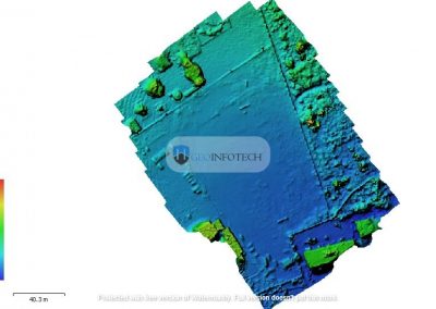
8.3 Surface Creation from COGO Points
Once topographic survey points have been imported and reviewed, they can be used directly to create a Civil 3D TIN (Triangulated Irregular Network) surface. A TIN surface interpolates elevations across the entire survey area and can be used to generate contour lines, volume calculations, slope analysis maps, and earthworks design surfaces. To add COGO points to a surface: in Toolspace, right-click the Surface object > Definition > Point Groups, and select the relevant point group. Civil 3D will immediately incorporate those points into the triangulation. Break lines: polylines that define hard feature edges such as road kerbs, drain inverts, or retaining walls: can be added as additional surface inputs to prevent the triangulation from interpolating incorrectly across slope discontinuities. The Errors and Troubleshooting that are common are revealed in Table 5.
Table 5: Common Errors and Troubleshooting
| Error | Likely Cause | Resolution |
| Points import to wrong location | PNEZD vs PENZD column swap (X and Y transposed). | Re-import with correct format; confirm E and N column assignments. |
| Points appear at incorrect elevation | Vertical unit mismatch (metres vs. feet). | Check Drawing Settings units; apply a scale factor or re-export from field software with correct units. |
| Duplicate point number warning | Same point number exists in current drawing. | Use the import option to add a numerical offset to incoming point numbers, or resolve in the source file. |
| Drawing appears blank after import | Extreme coordinate values placing points far off-screen. | Type Z then E to zoom extents; verify the CRS and that projection was applied before import. |
| LandXML import fails CRS check | Embedded CRS in LandXML file does not match Drawing CRS. | Match the drawing CRS to the LandXML file, or reproject the LandXML using third-party tools before importing. |
| Linework not generated by Field-to-Finish | Figure Prefix Database not configured, or codes misspelled in field. | Review and update Figure Prefix Database; check raw field codes for typos before processing. |
| Contours crossing over road kerbs | Break lines not added to surface definition. | Add road edge polylines as non-destructive break lines in the surface definition. |

- Best Practices and Recommendations
10.1 Pre-Survey Office Setup
In pre-survey office setup the following are required steps:
- Define and document the project CRS (including EPSG code) before fieldwork begins. Communicate this to all field crews.
- Create a standard Description Key Set and Figure Prefix Database template for your organisation. Apply it consistently across all projects.
- Establish a naming convention for Point Groups, layers, and surface names.
- Set up the Civil 3D drawing template (.dwt) with correct units, CRS, and layer structure so that every new project file inherits these settings automatically.
10.2 Field Data Collection
The essential requirements for field data collection are:
- Record the datum, projection, and geoid model in use at the start of every survey session,
- Capture a GPS check shot on an existing known control point at the start and end of each day to verify instrument setup,
- Use consistent, standardised feature codes from an agreed-upon field code library. Avoid ad hoc codes, and
- Export a preliminary point list from the data collector at the end of each field day and perform a visual check in a simple GIS tool or even Google Earth before leaving the site.
10.3 Office Processing
- Never import raw, unprocessed GNSS observation files directly into AutoCAD. Always reduce observations through dedicated survey processing software first,
- Maintain an original backup of every field data file before performing any editing or transformation,
- Import data into an isolated Civil 3D drawing for QA/QC review before merging into the project drawing,
- Use Point Group-level display control to isolate categories of points for review. Lock or freeze groups not currently being worked on and
- Document the import process: source file name, format used, date of import, operator name in a project log file.
- Conclusion
Importing GNSS and Total Station data into AutoCAD is a workflow that rewards careful preparation. The technical steps include selecting the right file format, applying coordinate transformations, configuring import formats, and creating well-organised COGO point structures are each individually straightforward, but errors at any stage propagate into the final drawing and can be difficult to detect retrospectively. AutoCAD Civil 3D provides the most comprehensive environment for survey data management, particularly through its COGO point model, Description Key Sets, Field-to-Finish automation, and TIN surface engine. For organisations using standard AutoCAD, scripting and third-party tools can reproduce much of this functionality, though with greater manual effort. The investment required to establish robust templates, coordinate system definitions, and description key libraries pays dividends on every subsequent project. Surveyors and CAD technicians who master this workflow will find that what was once a time-consuming manual process can be reduced to a rapid, reliable, and largely automated production step allowing more time to focus on design quality and engineering judgement.
References and Further Reading Materials
Autodesk, Inc. (2024). AutoCAD Civil 3D Help Documentation. Autodesk Knowledge Network.
Ghilani, C. D. & Wolf, P. R. (2022). Elementary Surveying: An Introduction to Geomatics. 15th ed. Pearson.
Schofield, W. & Breach, M. (2007). Engineering Surveying. 6th ed. Butterworth-Heinemann.
International Association of Geodesy (IAG). PROJ Coordinate Transformation Software Library. proj.org.
EPSG Geodetic Parameter Registry. epsg.org.
Trimble Inc. (2024). Trimble Access Field Software User Guide. Trimble Documentation Portal.
Leica Geosystems AG (2024). Captivate Field Software Reference Manual. Hexagon Documentation.
Autodesk University Proceedings (2023). Survey Data Management in Civil 3D: A Practitioner’s Guide. AU Online Library.